

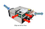
150g @ 5%
PlasmaBlock® Water Cooled

Product Summary
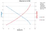
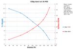
A medium size water-cooled unit with a small footprint and height when compared to other models. 1.7 lbs/day at 9.5% 3 LPM; 8 lbs/day at 4.7% weight 30 LPM (Oxygen or Concentrator). Useful pressure range: 5 – 98 psi. 23 kHz operating frequency for silent operation. Precise Linear Control with Turndown to 1%.
Product Details
![]() For added application information, see the PlasmaBlock® Application Guide manual.
For added application information, see the PlasmaBlock® Application Guide manual.
Models available
Refer to - Configuration Options Summary Sheet
- Silent, Rugged, Reliable, Safe, Efficient, Cost-effective, Compact, Light-Weight, Ceramic dielectrics.
- 1.7 lbs/day at 9.5% and 3 LPM; 8 lbs/day at 4.7% weight and 30 LPM (Oxygen or Concentrator).
- No exposed high-voltage safety hazards.
- Precise ozone control using Pulse Density Modulation (PDM) via potentiometer, 4/20ma or 0-10vdc.
- Precise Linear Control with Turndown to 1%.
- Useful pressure range: 5 – 98 psi.
- Now available with PlasmaVIEW® software (optional).
Design Features
- All high voltage is safely contained completely within the Plasma Block® thereby eliminating shock hazards and dirt buildup which can cause dangerous flashover. High-voltage wiring is booted and all metal grounded.
- Pre-mounted, seasoned and tested package sub-system which includes cells, heat exchangers, inlet gas flow meters, all inlet/outlet piping, manifolds, transformers, individual operational status indicators for each Plasma Block™, PDM controlled inverter, fans. Design uses the finest quality material and machining for maximum performance and efficiency. All framework components are epoxy powder-coated.
- Directly installable by UL 508a panel house,
- Modular design for service simplicity.
- Instant-ON ozone production -- no warm-up time. Ideal for ‘over-the-road’ applications.
- No fragile glass or ceramic cylinders which are prone to breakage during shipping or when used in ‘over-the-road’ applications.
- Micro Channel ® design results in high ozone concentration, reduced high-voltage levels, and more energy-efficient operation. Design has been mechanically and electrically optimized for oxygen. Requires concentrator or bottle feed of at least -60°F dew point, filtered, positive-pressure oxygen. Materials in the gap are ceramic and aluminum.
- PTI designed custom ceramic high-voltage feed thru provides the ultimate in high-voltage and high-pressure integrity, connection reliability, and safety.
- Precision-machined aluminum block eliminates inefficient hot spots and facilitates operation at high pressures as well as vacuum ride through, should a vacuum pulse occur. Only 1 psi drop with 60 LPM flow. As with any cell, the most predictable performance occurs in the positive-pressure domain. Maximum pressure 98 psi. certified by UL at 5x rating.
- 23 kHz operating frequency yields compact design, silent operation, lower cost, and no customer irritation due to high- pitched whine customarily present with older medium-frequency designs.
- Advanced design eliminates the possibility of ozone leakage from the body or fittings. The only ozone leak possible is at the customer-tightened ozone fitting. All non-metal materials are ozone rated.
- Military grade conformal coating eliminates problems associated with condensation and mold as well as greatly retarding damage caused by accidental ozone exposure.
- Ozone level automatically controlled to ± 1% from 170v to 260vac.
- The Inverter is a version of PTI’s popular SSD110. All control and interface features of the SSD110 are available in this product. To simplify customer use and serviceability, ALL of PTI’s Air and Liquid-cooled OEM systems use the same Input/Output control wiring connection points and signal levels. Said another way, you can unplug the control connector from a 30g Air system and plug it into this 150g Water system, and still be fully operational. No wiring or PLC changes are needed, and changes to your system user manual would not be necessary.
- Line voltage 208 - 240vac, single phase, 50/60hz, approx .6pf. Optional supply reactor available for improved power factor. Customer provided soft-start and phase-loss detect if needed.
- All gas connections are 3/8” NPT, water 3/8" OD.
- Pre-seasoned, calibrated and pre-adjusted to customers’ individual performance needs. Ready to install. Rigorous 100% performance as well as burn-in tests of all electricals, are conducted to ensure the highest level of product quality, reliability, and consistency.
- Patented design.
- There is an inherent pressure drop associated with each Plasma Block. This can vary depending on the desired flow. Verification of the outlet pressure, at the desired flow, of the Plasma Block is crucial in order to prevent a negative pressure drop in the Plasma Block. This will damage the Plasma Block internals and is not a warrantied repair.
Configuration options
PTI will set up and tune units to the customers desired specifications.
Oxygen pressure - (5 - 98 psi) (UL 5x rated)
Oxygen flow liters/minute - ( .2 - 40 Lpm) or equivalent SCFH
Heat load btu/hr = 4100
Inlet fittings (none, 1/4", 3/8", 8mm, 10mm, other)
Outlet fittings (none, 1/4", 3/8", 8mm, 10mm, other)
Weight Lbs (Kg) : 34.65 (15.71)
Related Manuals
(pdf format, view or download)
Installation Operation
Dimension Drawing
How to read the performance graphs
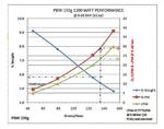
PlasmaBlock Performance Specs (heat dissipation, current, ozone output)
DAT210 is the standard control circuit board for this unit.
DAT210 Quick Start Manual
DAT210 Installation and Operation Manual
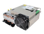
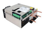
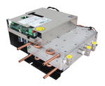
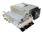
Product Photos

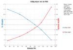
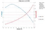
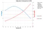
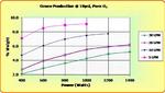
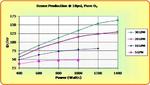
Output Performance Charts


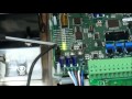
Training and Instructional Videos
DAT210 Set Power Point
DAT210 Start Button Sweep
DAT210 New Profile Procedure
DAT210 Normal Running
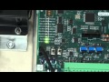
DAT210 LED Fault Indicators
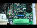
DAT210 Connection Safety Considerations
DAT210 On Delay Timer
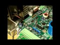
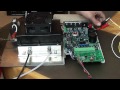
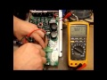
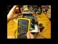
Fuse and Power Supply Testing
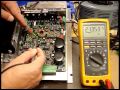
IGBT and Diode Bridge Testing
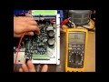
16 Pin Kit Testing
DAT210 Firmware 3 1
SSD110 tuning
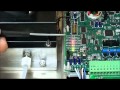
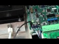
Maintenance and Repair Videos
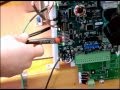
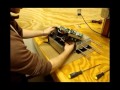
Replacing the Power Supply - 150g Plasma Block
Step by step guidance on replacing the power supply
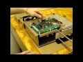
Re Assembly of 150g Plasma Block
Re Assembly of the 150g Plasma Block after replacing the power supply.
Installation Drawings


