

DAT210 Inverter Assembly with Power Conditioning Module (code 70250-4 120v, 70250-5 220v)

Product Summary
The DAT210 Inverter Assembly solves several circuit problems that shorten component life and simplifies assembly of products at an install site. For use with 240v 3Ø, 25 amp max or 240v single phase. To optimize power factor correction for other currents, see this table.
Product Details
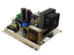
![]() The DAT210 Inverter Assembly solves several circuit problems that shorten component life and simplifies assembly of products at an install site. For use with 240v 3Ø, 25 amp max or 240v single phase. To optimize power factor correction for other currents, see this table.
The DAT210 Inverter Assembly solves several circuit problems that shorten component life and simplifies assembly of products at an install site. For use with 240v 3Ø, 25 amp max or 240v single phase. To optimize power factor correction for other currents, see this table.
Benefits and Features of the Assembly
- Support 1Ø and 3Ø mains
- Eliminates transient voltage spikes to DAT210 Inverters and Plasma Block Units
often caused by contact interruption at full power. - Includes dc rectification, softcharge, power factor correction (.7 - .94 power factor),
transient and line noise filtering. Absorbs transient energy from its specific load,
not entire large system energy - Soft start feature to prevent startup current surges from weakening circuit breakers
- Power factor correction to 0.95 for accurate current measurements
- Three phase 208 – 240 VAC rectification for single phase high frequency output
- 4.5 KW rating (P/N 70250-1) 2.2 KW (P/N 70250), dependent on operating frequency.
Additional cooling is suggested. - DAT210 (Digital Auto Tuning) compensates for generator pressure and flow changes automatically
- No inverter and transformer failure due to brownout, operating changes or cell fault
- Reduces OEM inventory
- Reduces expense of installing many components to achieve the same results
- Tested assembly reduces installation mistakes
- Completes electronics package required for ozone generators
- Reduces inverter mains current by about 50%, extends inverter component life
Connections

1.) Positive power output to DAT210 board. Connects to "+BUS" 0.25" quick connect tab on circuit board.
2.) Negative power output to DAT210 board. Connects to "-BUS" 0.25" quick connect tab on circuit board.
3.) Incoming 3 phase power. 0.25" quick connect tabs. Customr supplied fusing required.
4.) AC reference signal to DAT210 board. Connect to "INPUT" connector (CON2) on circuit board.

Connection polarity for 5V dc to Con3 is critical. Incorrect wiring will damage the board !
Wire guage of 22awg is recommended.
1. Pin 1 is for the negative 5Vdc connection. This should be connected to pin 3 on the 16 pin
connector on the DAT210 board (marked as CON12 on the circuit board).
2. Pin2 is for the positive 5Vdc connection. This should be connected to pin 5 on the 16 pin
connector on the DAT210 board.
3. Alternately : connect to customer PLC for soft charge management. Polarity is critical !!!
Plasma Technics, Inc.® (PTI) assumes no responsibility or liability for specific applications results.
PTI supplies only components for ozone systems and not the complete system. The complete system
is the responsibility of the ozone system manufacturer and/or others involved in a specific project.
Related Manuals
(pdf format, view or download)
Product Photos

Training and Instructional Videos
DAT210 Set Power Point
DAT210 Start Button Sweep
DAT210 New Profile Procedure
DAT210 Normal Running
DAT210 LED Fault Indicators
DAT210 Connection Safety Considerations
DAT210 On Delay Timer
Fuse and Power Supply Testing
IGBT and Diode Bridge Testing
16 Pin Kit Testing
DAT210 Firmware 3 1
Installation Drawings


