

DAT210 Digital Auto Tune Inverter 250w - 4kw / 50hz - 30khz

Product Summary
DAT210 The new Micro-controller design that automatically determines the optimum system operating frequency (resonance). This product makes high-efficiency self optimizing systems available to everyone. This single-phase inverter provides a linear means to adjust corona by using Pulse Density Modulation (PDM), with frequencies up to 30khz. Microcontroller design provides unprecedented control integration.
Product Details
![]() The DAT210 is a new Microcontroller design that automatically determines the optimum system operating frequency (resonance). Years in the making, this technology will, for the first time, make high-efficiency self optimizing systems available to everyone. This single-phase inverter provides a linear means to adjust corona by using Pulse Density Modulation (PDM), with frequencies up to 30khz. This control scheme allows the inverter to use the full potential of the IGBTs by reducing the usual high-frequency switching losses. Automatic buss-voltage compensation stabilizes the output as power line conditions change. PTI has specifically designed transformers to mate with the DAT210, thereby providing a complete high- voltage solution
The DAT210 is a new Microcontroller design that automatically determines the optimum system operating frequency (resonance). Years in the making, this technology will, for the first time, make high-efficiency self optimizing systems available to everyone. This single-phase inverter provides a linear means to adjust corona by using Pulse Density Modulation (PDM), with frequencies up to 30khz. This control scheme allows the inverter to use the full potential of the IGBTs by reducing the usual high-frequency switching losses. Automatic buss-voltage compensation stabilizes the output as power line conditions change. PTI has specifically designed transformers to mate with the DAT210, thereby providing a complete high- voltage solution
Applications
- Ozone system variable-frequency voltage drive and Pulse Density Modulation.
- Non-thermal plasma or cold plasma systems.
- Applications requiring good plasma coverage at extreme turn down, such as 1%.
- Corona Treatment and Static Eliminator systems.
- High-frequency, high-current supplies for laboratory use.
- DC to Single-phase output conversion for crane and gantry lighting.
- Now available with PlasmaVIEW ® software.
- Programming and Troubleshooting.
- Web Interactive Troubleshooting.
Features
- Microcontroller design provides unprecedented control integration. Formerly unmanageable in large systems, automatically tuning maintains maximum system efficiency and holds power constant as system conditions that effect performance may drift.
- Selections for full automatic system tuning, semi-automatic and manual modes.
- Advanced power control via Pulse Density Modulation (PDM) yields linear power (Ozone) output vs. command signal, even at high turn-down. This is only possible when PDM is used.
- Extensive two tier fault enunciation maximizes up-time and simplifies service diagnostics. Latched fault indicators retain fault status until serviced.
- User-adjustable HIGH and LOW load-current bracketing. Either high current or low current produce a fault which is reported to the terminal strip as well as LEDs, which can then be handled as a soft fault or hard fault. Soft means a user-provided PLC can decide what action is taken before the inverter is disengauged. A hard fault will automatically provide an OFF command to disengage the inverter output.
- Pulse Width and Frequency control in manual mode provide for complete system flexibility.
- Onboard potentiometers to control frequency, power (PDM), and output voltage (Pulse Width) can be jumpered in or out individually, if off-board control is desired.
- Inputs easily interface to PLC or computer. 4-20 ma input or 0-20 ma control of power (PDM) for simple and linear ORP interface, if desired. Also, jumper configurability for 0-10vdc allows interfacing to all common closed- loop control devices. Frequency and Voltage (Pulse Width) optionally controlled via 0 – 10vdc.
- Additional user-terminal strip interfaces: Output ON (implies no faults); scaled buss volts; scaled buss current; 1x inverter clock frequency, soft / (latched) hard fault.
- Safety lockouts and automatic-fault shutdown should short-circuit or over-temperature conditions occur. Fault status is latched and is reported via LEDS to aid technicians. Indicators include: Output ON, Instantaneous, and long-term over current, over temp.
- PDM, Voltage and Frequency potentiometers have their own jumper selection for on board control if desired.
- Push-On, Push-Off or toggle-switch control, inputs and simulates contact logic for simple management of ON/OFF function.
- Buss-Voltage Compensation maintains nearly constant output voltage should line voltage drift. Compensation is automatically scaled for 120v and 240v operation.
- Control connections of the essential I/O functions are the same as the SSD110 and Plasma Block®.
- Full pulse-by-pulse current limit control for all power output devices for reliable operation.
- Short input power loss ride-through stabilizes performance during line-voltage fluctuations.
- All control connections are fully isolated from power line reference to enable simple and safe connection to other equipment.
- Normal frequency range of 50hz, adjustable to 30khz with built-in IGBT protection circuits.
- Military grade conformal coating eliminates problems associated with condensation and mold as well as greatly retarding damaged caused by accidental ozone exposure.
Example DAT210 Outputs

Full Frequency / Full RMS Voltage

Sizing
|
Part Number |
Device Rating/Phase (ARMS) |
Inverter Output/Phase (ARMS) |
Output Voltage (VRMS) |
Output Power (KVA) |
PTI Transformers Leg |
| DAT210 | 25.0 | 15.0 | 240 / 120 | 3.6 / 1.8 |
Input Specifications
AC input 90 to 264 (VRMS) single-phase, 50/60hz. DC input voltage 120 to 373 (VDC)
Forced cooling may be required in addition to the provided fan, and is to be provided by customer.
Consult factory for pricing and availability of unlisted models.
Related Manuals
(pdf format, view or download)
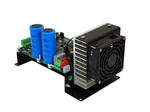
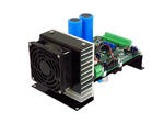
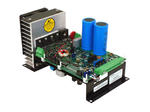
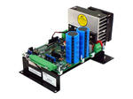
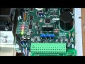
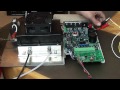
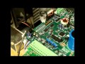
Product Photos

Training and Instructional Videos
DAT210 Set Power Point
DAT210 Start Button Sweep
DAT210 New Profile Procedure
DAT210 Normal Running
DAT210 LED Fault Indicators
DAT210 Connection Safety Considerations
DAT210 On Delay Timer
Fuse and Power Supply Testing
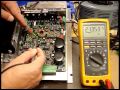
IGBT and Diode Bridge Testing
16 Pin Kit Testing
DAT210 Firmware 3 1
Installation Drawings
